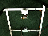
Carbon fiber road forks make a great upgrade over alloy ones and could save as much as 1kg in weight, but the carbon makes them a more difficult to fit. Firstly you'll need to fit the crown race to the forks, whacking this on in the usual way seemed like it was going to end in disaster with carbon forks. The solution to this is to use a hacksaw to put a slit in the race so it will slide on without any fuss, some races come with a slit cut them already and this seems to be a great idea - the race is compressed by the inner ring of the lower bearing so it's not going anywhere.
Next is fitting the brake caliper. The forks I had were the silver Planet X ones which are much deeper that alloy forks where the brake caliper bolts on, this is not necessarily a problem as long as the 3 distances (A, B and C - see diagram) within the fork are sensible. The first problem I had was that C was way too long so the threads of the brake (purple) caliper bolt (green) would only engage enough for a couple of turns without the serrated washer (blue bit). I had a set of nuts (grey bits) of different lengths but a problem with C means this will not help. Ideally a setup like is pictured would be the best, where when tightened up shoulder of the nut is pressing on the forks (between A and B). If the nut is too long it's the end of the nut that will press on the forks (between B and C) which is not ideal. With my forks I had to drill them to make B longer (and C shorter), this was not a fun experience and took a lot of measuring and careful drilling to make sure B was the right length for the nut I was using and C was the right length for the bolt on the brake calipers. You need about 10mm of thread engagement between the bolt and nut, I was fitting Shimano Tiagra brakes and I think I used the standard nut that came with them. The length of B I don't think is critical and as long as you don't drill all the way through the forks it should be fine, you need to make sure the caliper bolt thread does not go too far through the nut otherwise you can't fit an allen key into the nut to tighten it up! If you're drilling you are best off marking the bit with tape and doing just a couple of mm at a time then test fitting to see how things are looking :).
Mostly Fixing...
Sunday 10 April 2016
Saturday 21 July 2012
Bosch Dishwasher Draining Problem Fixed!
Recently we acquired a used Bosh Dishwasher (a SGS6301GB/12 no less) which was supposed working fine but had 2 serious issues; firstly the door seal failed, this was pretty easy and cheap to replace, there are videos on line step through this in detail. Secondly the dishwasher seemed to finish a program too early (with the time changing to 0) and leave a load of water in the bottom, not enough to spill out onto the floor but it was clearly not right. Sometimes it would get to the end of a program but there would still be water left in the bottom. It seemed to be running the drain pump ok but for some reason it wasn't working. This is a very common problem with Bosch dishwashers if you look on the forums, not sure what exactly fixed mine but here is what I did.
1 - Check and clean filters, check for debris around drain pump impeller and damage (remove torx T20 screw in impeller cover),check for kinks and blockages in drain hose. No difference..
2 - Take off left side panel (lid slides back to remove, then take out 2 x T20 screws on front edge) and look at 'metering tank' (crazy tall transparent plastic thing that water/drain runs through). Mine had a load of unpleasant black stuff in the top left hand corner around some kind of air inlet/outlet value for the drain water. Take it out (hoses just pop off) and clean it out by sloshing hot water around inside it violently). Worked ok for a couple of days before problem returned.
3 - Remove and clean drain check valve (pull on little black rubber tab under impeller cover), at this point I noticed one of the blades on the impeller was missing. I ordered a new pump and a new check valve (it seems the rubber ones deform/swell causing drainage problems and have been replaced with a clear plastic version).
4 - Remove left side panel, remove low front panels for access to the pump (unclip/slide off the plastic kick-plate then remove metal piece that runs under the bottom of the door with a T20 screw holding it on at each side). Take out complete 'pressure chamber' assembly, dismantle completely and clean (all pops apart but needs to be done very carefully) - mine had quite a lot of fatty looking deposit in it, rather disgusting but easily rinsed out with hot water. There is a plastic pipe that runs from the pressure chamber to the front of the sump next to the drain pump, this just pulls out at both ends and mine had a lot of fatty gunk in it.The pump just twists and slides out, same deal to get the new pump back in - removing that front panel thing gives just enough access to make this possible. I also took out the control board that sits bind the switches at the top of the door (just take out all the torx screws and it comes apart). There is a rather annoying cover over the board and after some careful unclipping along 3 sides to remove it the main board can pop out. Mine looked like it had some dodgy joints on the pins of the relays and around the small transformer and diodes - I'm not an expert on this but look for a faint band around the circumference of the solder joint. I re-flowed the joins with a bit of extra solder then cleaned up around the soldering and all the edges where the connectors slide on. This all took a couple of hours but it worked! Now draining perfectly and just leaving a very small amount of water at the bottom of the filters like dishwashers do.
5 - Fit shiny new plastic drain check valve when it finally turns up...
By step 4 I was pretty determined to fix the thing and it's hard to pinpoint what the problem was exactly. I'd be surprised if the impeller blade caused the issue or the control board, I think it more likely to be caused by the fatty gunk in the pressure chamber and associated hose (a lot of the info I found on forums supports this). Although, if you're going to the bother of taking it all apart it's probably worth sticking in a new pump as they're pretty cheap from ebay. Hope this info helps someone out there! Below are the pics I took for reference when I was doing it, of control board, pressure chamber, metering tank, and pump.
Wednesday 11 July 2012
Still Building a Multi-touch Tabletop
The previous incarnation of the multi-touch tabletop has some issues with the top mirror occluding the camera, heat problems and other niggling issues. To fix this I adopted a simpler single mirror approach with the projector slightly outside the footprint of the table, this made locating the cameras and IR illumination trivial, the IR illuminators reflect off a rounded piece of plastic covered with paper which seems to give good even illumination (though the illuminators are very powerful and from high-spec CCTV equipment). Using CCV 1.4 and the CL Eye driver/platform the tracking is pretty much perfect over the whole projection area (which takes up most of the area inside the black rectangle).
Tuesday 10 July 2012
£5 Tripath TA2024 Amplifier
The Tripath TA2024 has a cult following after it appear in the Sonic Impact T-amp and gained a lot of acclaim. The favourite chips in this genre are the TA2024 with 11 watts into 4 ohm, the TA2020 with around 20 watts, and TK2050 with 50watts - all very efficient switching-based class D amps. There is a large modding scene and a lot of small companies selling boards using these chips with high-quality components. A Ta2024 board can be had for around £5 delivered from ebay and just needs a 12v supply providing a couple of amps to get it going - the components are as cheap as it gets but they sound great! I mounted mine in a small project box with a volume pot and some cheapo gold connectors. I played around with some different input caps and replaced the power caps with much bigger ones - I found it sounded good with 2.2uF electrolytics (as Tripath suggest in the data sheets) and gave a reasonable amount of bass.
WiFi Boiler Monitoring Arduino-Powered Current Cost Meter
The Current Cost electricity monitor is probably the most hacker-friendly energy monitor, spitting out data over a serial line in XML at periodic intervals and supporting simple add-on modules. This projects combines a Current Cost meter with a Roving Networks WiFly module, a set of thermistors, and an Arduino. The WiFly module is trivial to configure once you know what configuration you need, so much so that you can configure it to combine data received over a serial line with a pre defined HTTP post!
50 Watt Power Amplifier Using Maplin Kits
In about 1984 I built a power amplifier for a school project using Maplin kits, 2 of these (the link has full instructions on how to build the kits). 18 Years on I decided to take a look at them and see if they still worked - they did but the wiring inside was pretty hopeless. I re-built the rectification circuit with dual rectifiers and snubbers, sorted out the internal wiring and replaced all the poor quality ageing caps in the important parts of the boards, added and mains-loop breaker. I also replaced all the audio connectors on the front but his was after the pics below were taken. The case isn't the most beautiful creation in the world but it sounds great!
Repairing Canon EF 28mm
A common fault on the Canon EF 28mm series of lenses in the zoom jamming, this is easy to fix but the rear of the lens had to be removed and a very fragile connector de-soldered and removed from the PCB. Once this has been done just back off then tighten up the big screw to fix.
Subscribe to:
Posts (Atom)